


Projector status LED
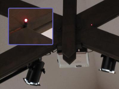
A few years ago, we installed a projector in the church sanctuary. It is mounted to the front of an exposed truss, and the laptop that controls the video display is in the back of the sanctuary. To turn the projector on or off, we have an IR remote that is powerful enough to bounce off the front wall when activated from the back of the sanctuary. However, it is not 100% effective, and sometimes we need to press the button more than once. The power status LED on the projector is not visible from the back of the sanctuary, so we still have to walk up front to verify that the projector is indeed on or off.
This project solves that problem. It is a smart power status LED that we can see from the back of the sanctuary, powered by (and communicating with) the projector's RS-232 control port.
Design features:
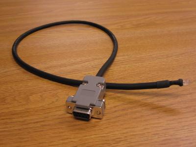
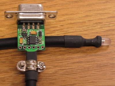
- Bicolor status LED on a short wire can be pointed in any direction
- LED lights green when the projector is on, red when the projector is off, or flashing red when the projector lamp is cooling down.
- Communicates with a Hitachi projector using the RS-232 serial protocol
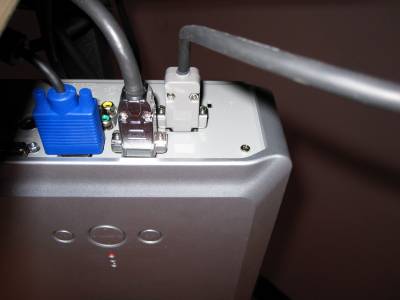
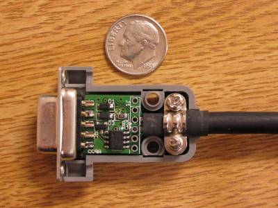
- Circuit is fully contained within the 9-pin D-sub backshell
- No external power supply necessary
Construction
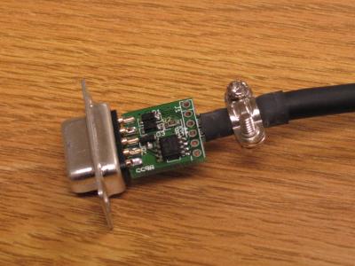
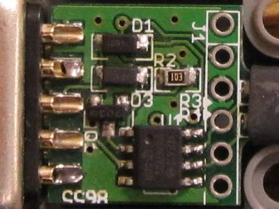
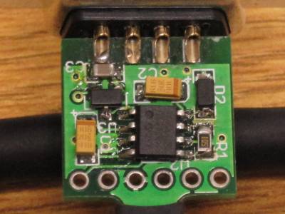
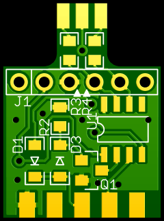
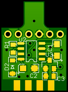
The circuit is printed on a dual-layer PCB that is designed to fit between the rows of solder cups on a standard 9-pin D-sub connector. The cable is 3-conductor stranded microphone cable with thick, flexible rubberized insulation.
The components are hand-soldered onto the PCB using a small 12W needle-tip iron. The cable is soldered to the PCB at three surface pads at the edge of the board. The LED is free-hanging soldered to the other end of the cable.
Shrink tubing provides strain relief and electrical insulation at both ends of the cable. The LED leads are insulated from each other by small bits of shrink tubing inside the outer tube.
Additional strain releif is provided by the cable clamp that is included with the D-sub backshell.
Project status
The project is complete, and has been installed and operating in the church without incident for several months as of November 2009.
Bill of materials
| C1,C2 - | Charge pump capacitors: | 10µF, ≥15V | (3216 metric) | Any appropriate |
| C3 - | Stabilizing capacitor: | 1µF | (0805) | Any appropriate |
| D1 - | Supply rectifier diode: | Schottky, VR≥30V | (SOD-123) | ON Semiconductor BAT54T1G |
| D2 - | Charge pump start-up diode: | Schottky, VR≥15V | (SOD-123) | ON Semiconductor BAT54T1G |
| D3 - | Signal rectifier diode: | Schottky, VR≥30V | (SOD-123) | ON Semiconductor BAT54T1G |
| J1 - | Programming header: | (Not placed - program the microcontroller by holding a free-hanging male header in these holes) | ||
| J2 - | Wire to bicolor LED: | (Solder 3-conductor cable to these pads) | ||
| J3 - | D-sub connector: | Solder cup | (DE9/DB9) | Norcomp 171-009-203L001 |
| R1 - | Charge pump start-up pull-down resistor: | 1MΩ | (0805) | Any appropriate |
| R2 - | Receive signal pull-down resistor: | 10kΩ | (0805) | Any appropriate |
| R3 - | Current-limiting resistor for green LED: | 1kΩ | (0805) | Any appropriate |
| R4 - | Current-limiting resistor for red LED: | 2.2kΩ | (0805) | Any appropriate |
| Q1 - | Transistor for RS-232 receive signal: | N-channel MOSFET, small signal, VGS≥15V | (SOT23) | ON Semiconductor 2N7002ET1G |
| U1 - | Microcontroller: | 8-bit PIC, 1MIPS | (SOIC-8) | Microchip PIC12F615 |
| U2 - | Charge pump voltage doubler: | -12V input | (SOIC-8) | Microchip TC1044SEOA |
| U3 - | Voltage regulator: | +12V input, 5V output, LDO | (SOT23A) | Microchip MCP1702T-5002E/CB |
| N/A - | Backshell hood: | Plastic backshell hood | (DE9/DB9) | Norcomp 977-009-010R031 |
| N/A - | Bicolor LED: | Red/green, high-efficiency | (T-1¾) | Kingbright WP59SRSGW/CC |
| N/A - | Cable for LED: | 3-conductor stranded (2 wires plus shield), 18" long | [Surplus microphone cable] | |
| N/A - | PCB: | Special order | From BatchPCB | |
Design files
IMPORTANT: Please measure the RS-232 signal voltage before connecting this circuit. The power supply can only support up to 12 volts on the RS-232 signal lines, and some serial ports may put out as much as 15 volts.
The board is designed to be wedged between the rows of solder cups on the D-sub connector.
Design details
Power supply
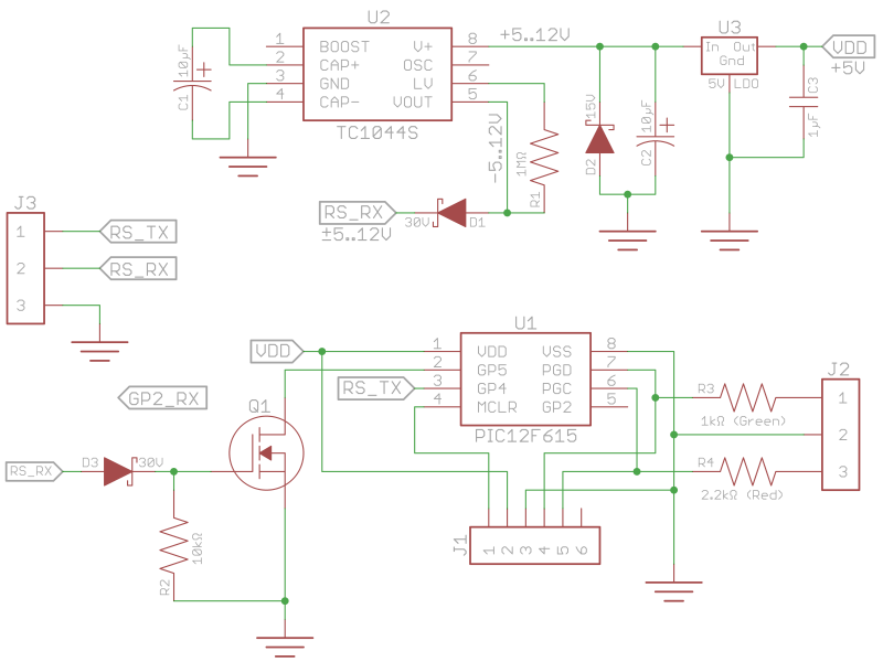
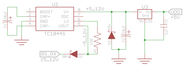
The outgoing signal line on a typical RS-232 serial port can supply a few milliamps of current somewhere between 5 and 15 volts. The signal wire is usually negative with respect to the ground pin, but swings positive when there's a zero bit on the line. The Hitachi projector that I'm dealing with outputs -9.8V with no load, sagging to -5V at 6mA load.
In order to get +5V power supply to the microcontroller and keep the same ground reference, the circuit first doubles the voltage difference between the negative supply and ground to generate a positive supply, then regulates the positive supply down to +5V. The PIC doesn't pull that much current at all, and the bicolor LED I've chosen lights acceptably at just 3mA for green, and 1.5mA for red.
One concern is that when the projector is sending data, the negative power supply is intermittent. Through testing, however, I've found that the capacitors I've chosen are large enough to sustain the PIC operation and the LED during the short 2-byte responses that the projector sends, without a noticeable drop in the LED brightness.
Transmitting commands to the projector
To transmit data to the projector, I just have the signal line tied to an output pin on the PIC. Even though 0V is not a valid signal state for RS-232, the swing between 0 and +4.8V is enough for the projector to correctly receive the serial data.
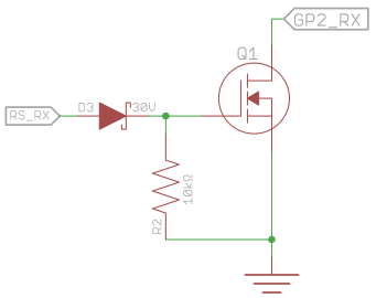
Receiving responses from the projector
To receive data from the projector, I have to translate the ±5..15V RS-232 signal to logic levels (0..5V). To do that, I use a rectifier diode to cut out the negative voltages, then a MOSFET to serve as an open-collector output attached to one of the input pins on the PIC, which has internal pull-up resistors. I added a pull-down resistor on the MOSFET gate, so that it opens and closes reliably. Through trial and error, I found that 1MΩ doesn't drain the gate charge fast enough, but 10kΩ works just fine.
PIC peripherals used
- GPIO inputs with internal pull-up resistors - RS-232 rx line
- GPIO outputs - RS-232 tx line, bicolor LED
- Timer2 - Periodic status poll timer
Component selection
Note: I follow the rules of significant figures for these calculations. Be careful about the unit magnitudes (kilo-, nano-, etc.) during multiplication and division.
C1,C2,R1 - Charge pump components
The values for the charge pump capacitors and resistor were taken from the voltage doubler datasheet. They need to be able to handle at least 15V, and probably should be at least 20V. Tantalum capacitors have the smallest footprint for the best low-volume price that I found. If you are buying more than five capacitors, the 1206 ceramic type, which is cheaper in volume, should also work.
C3 - Stabilizing capacitor for voltage regulator
The value for this capacitor was taken from the LDO voltage regulator datasheet.
D1,D2,D3
The diodes need to handle a voltage difference of at least 30V when connected between the positive and negative supply buses, or 15V when connected between a supply bus and the signal ground.
R2 - Receive signal pull-down resistor
This resistor pulls the MOSFET gate down to 0V when the RS-232 signal is marking (negative). I chose the value of this resistor by trial-and-error when I was breadboarding the circuit. Later, I did the math to understand why 10kΩ works and 1MΩ does not.
Click here to show the math.
R3 - Current-limiting resistor for green LED
Click here to show the math.
R4 - Current-limiting resistor for red LED
Click here to show the math.
Firmware components
The firmware has a few reusable algorithms:
- Simple cycle-accurate delay loops
- RS-232 single-byte transmit procedure (19200bps)
- RS-232 single-byte receive procedure (19200bps)
Possible improvements
After building this device, I recognized a few improvements that could be made to improve RS-232 compliance and reduce the cost by a few pennies. Of course, to implement these ideas you would need to redesign the PCB layout.
- R2 and D3 are unnecessary, since the MOSFET gate can easily handle negative voltages.
- The power supply could be redesigned to use an IC that can handle a 15V supply.
- The code could be rewritten to run on the smaller, less expensive PIC10 microcontroller.